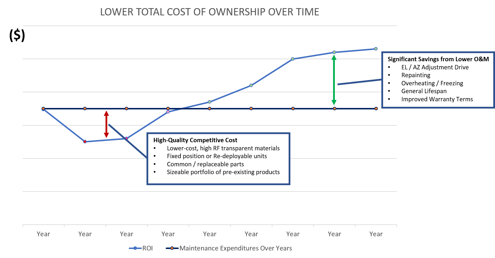
Life-Cycle Maintenance
Upfront cost for RF shelters paid back through lower O&M Expenses
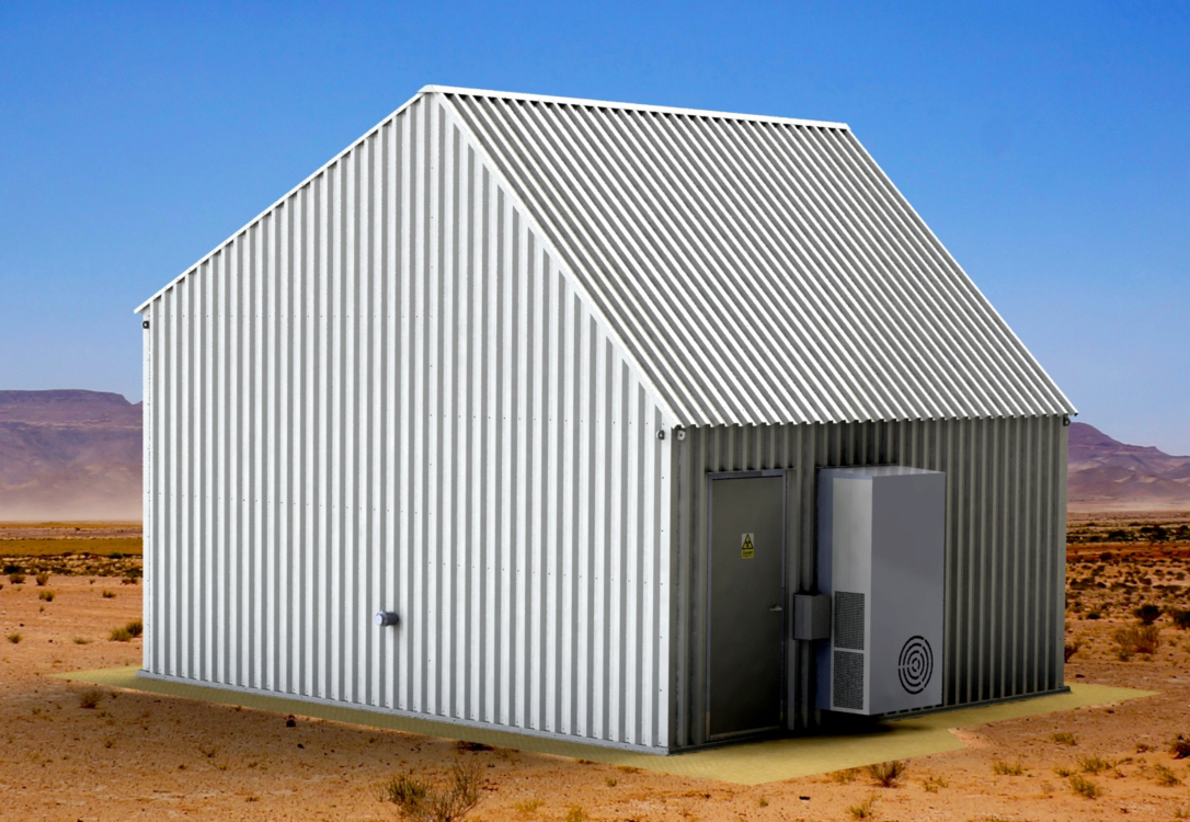
CFG Systems Shelters have been proven to increase and enhance the useful life of satellite dish antenna in a variety of extreme weather conditions, whether it’s preventing damage from extreme heat, wind, sand, hail, or snow. CFG Systems Shelters have an attractive payback profile through reduced O&M expenses for deployed antennas. As an added benefit, most Shelters are redeployable; allowing them to be relocated along with the antenna.
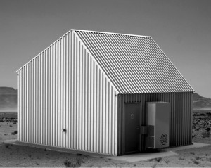 RF Shelters are built to withstand extreme weather environments
- High-strength structural beams support each shelter’s superstructure
- All shelters are P.E. stamped per requirements of each specific exposure zone requirements
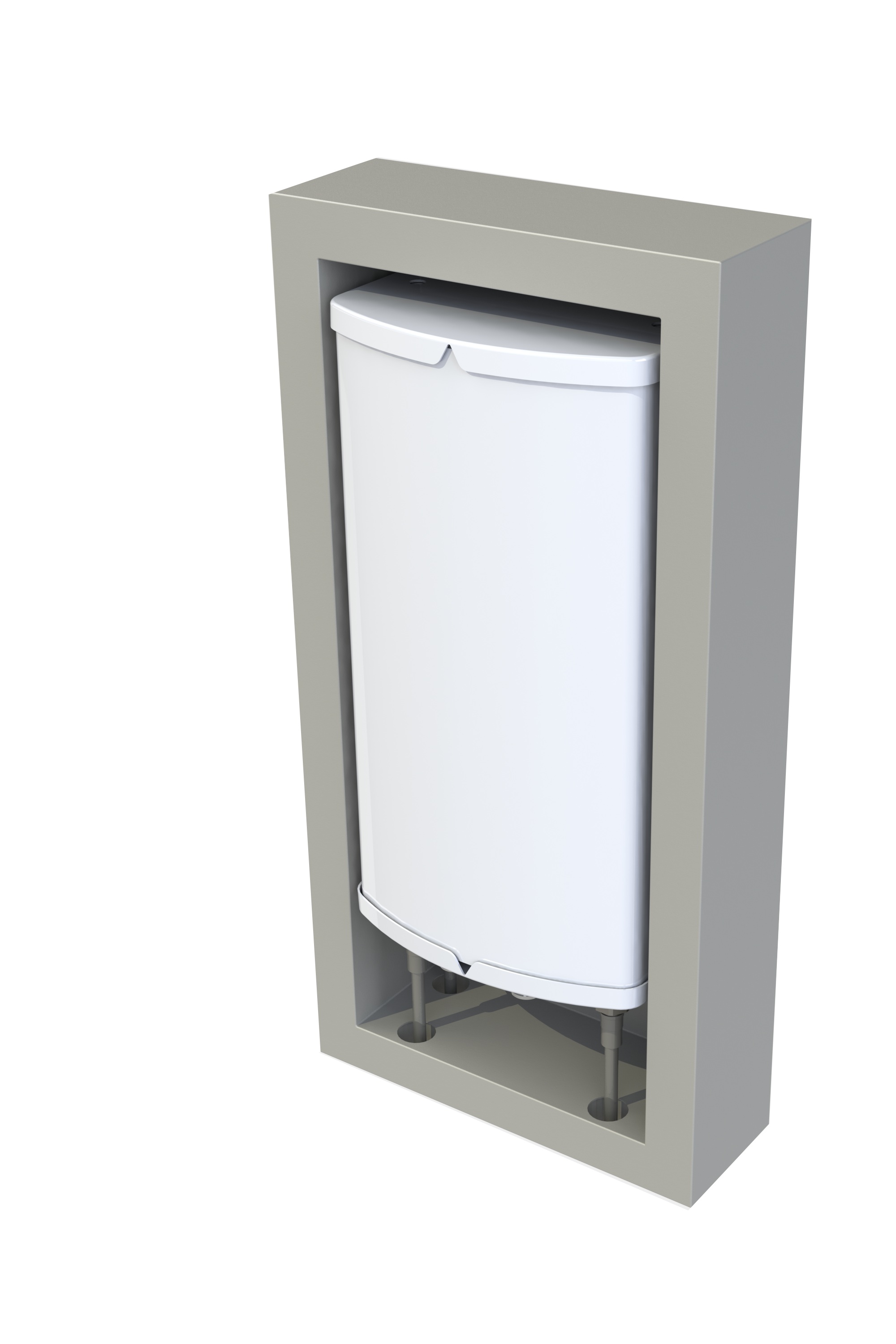
- Environmental control units (air movers) are appropriately selected based on shelter size / needs
- HVAC / heating units to moderate extreme temperature fluctuations
- Sand skirting at base eliminates ingress from blowing sand
- Pitched or sloped roofing to shed water, ice, and snow
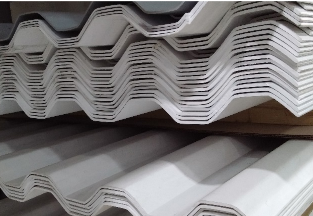
Thermoplastic panels are:
- Impenetrable to water and other weather elements
- Chemically inert to resist environmental degradation
- Resistant to impact loads from hail, rocks, and sand
- Able to withstand high wind-loading and temperature extremes without warping or breaking
- Weather stripped with special seal strips to prevent water ingress from driving rain
- Unaffected by actinic radiation / RF
Life Cylce Maintenance
Back-Lobe Suppression
Improves operating performance of close-proximity antennas
While results will vary from antenna model to antenna model and from frequency to frequency, the plots below are representative of the performance improvements typically achieved. The blue plots represent the far field, co-polarized radiation patterns and the red plots represent the far field, cross-polarized radiation patterns. Here, the front-to-back ratio, measured within the 30° cone behind the antenna improved from 16 dB to 28 dB with the back lobe suppressor installed.
As is typical with most ±45° polarized antennas, cross-pol radiation in the lower frequency bands is often higher than the level indicated in the planning tool patterns. This is not due to antenna manufactures trying to hide information. Rather, it is due to the accepted industry standard that planning tool patterns are derived from co-polarized radiation patterns rather than total energy radiation patterns. While co-pol patterns may be perfectly adequate for predicting performance at typical macro sectors, they may not adequately predict performance at tightly spaced stadium sectors. ConcealFab’s back lobe suppressors provide an effective way to clean-up unwanted back lobe radiation when predicted performance does not match actual performance.
Back-Lobe Suppression

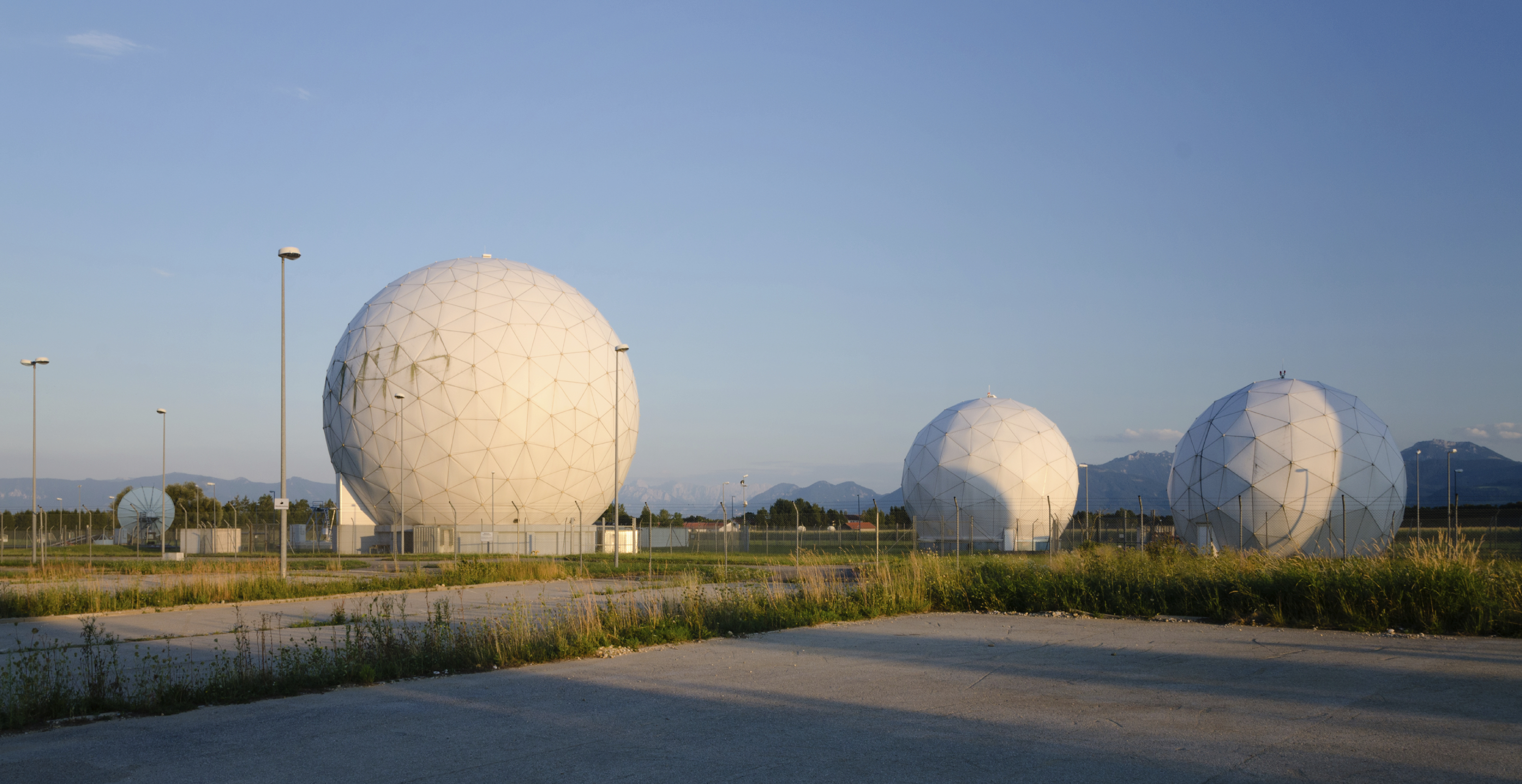
Concealment Capabilities
- Designed and configured to blend into most native environments
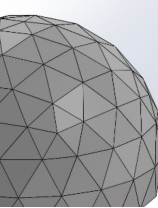
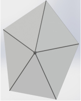
- High-Frequency Radomes
- Significant improvement in RF Attenuation vs.
- Fiberglass
High Frequency Radomes